The Concept
I sometimes have trouble waking up in the morning, so I wanted to make a challenge for myself whenever I try to turn off my alarm clock. I already made a memory game, and I made a simple design for outputting to a 7-segment LED display, so I decided I wanted to integrate those designs into an alarm clock.
The Design
The box
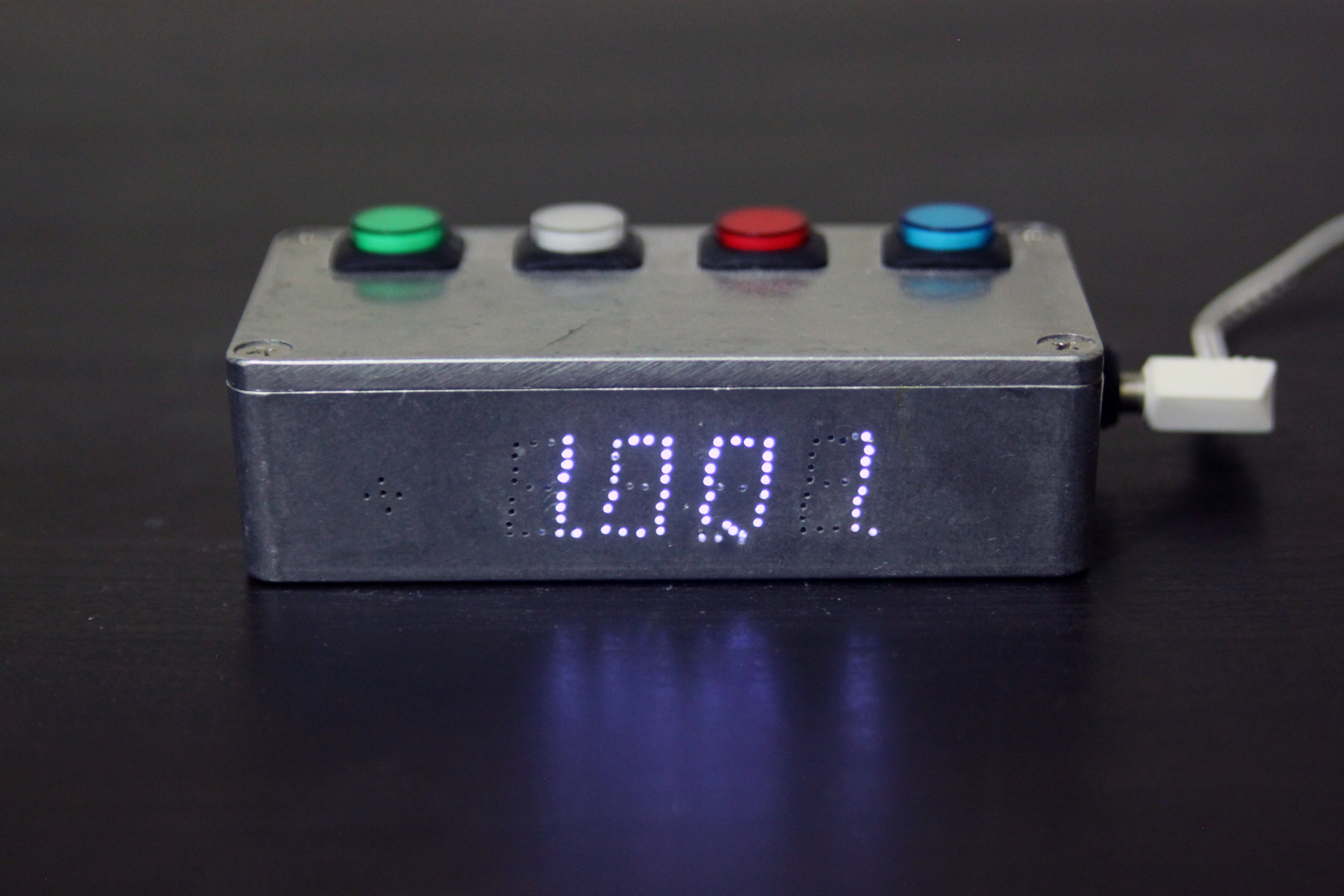
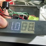
I found an inexpensive aluminum project box online and decided to use it as the body for the alarm clock. I found some buttons with built-in LEDs for the memory game portion, and I decided to strategically drill holes in the front of the box to allow the time display to shine through. Like I mention in the demo video, I didn’t do a great job of this.
The Circuit Board
The main electrical components I have on the PCB are:
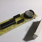
- ATMega328 – system logic and I/O
- DS1307 – Real Time Clock
- 3V coin cell for real time clock
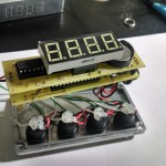
- LED Display
- MAX7219 for LCD screen
- Buzzer for alarm
- Resistors, capacitors, and crystal oscillators
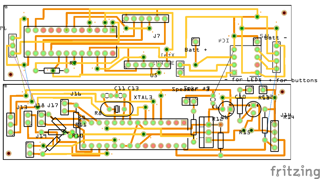
In order to fit everything into the small project box, I went with a stacking PCB design with two 2-layer boards.
-
- The first layer
-
- Second layer added
-
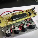
- Boards fitting into the case
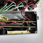
The buttons and lights are connected by wires to the circuit board where they are directly soldered on. In future, I would like to modify this to a plug-in connection to make it easier to take the lid off for battery replacement.
Features
- Requires a memory game to be beaten to turn off alarm
- All functions of alarm clock are controlled by 4 memory game buttons
- Buttons light up whenever pressed for feedback
- Intuitive alarm and time setting
- Adjustable brightness
- Adjustable difficulty
- 12/24 hour time display modes
Demo
Making Of
-
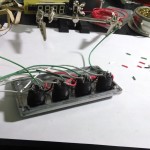
- Attaching wires to buttons
-
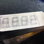
- Marking LED screen segments
-
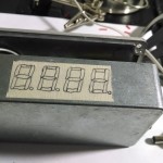
- The end result
-
- A guide for drilling holes
-
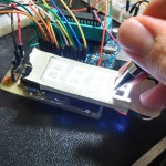
- Halfway through
-
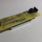
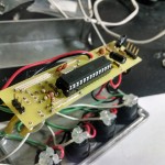
- The underside of the LED display board
-
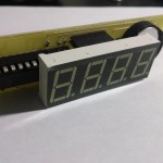
- Top side of the board
-
- View with LED display detached
-
- The bottom board with buttons and buzzer attached
-
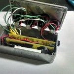
- Everything in the box!
The code and PCB schematics can be found on my GitHub.